REPLACING THE FRONT DOOR WINDOW REGULATOR CLIPS
The following DIY outlines the procedure for removing the window regulator carrier panel, replacing the window regulator clips and the door lock module on a MKIV Golf/Bora/Jetta. Please do these procedures at your own risk and be ready to make small adjustments while doing them. Also, please be observant while removing parts so that they go back together correctly.
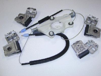
The clips were part of the Window Regulator Repair Kit which cost £47.36 + VAT from VW Dealers or Buy one for less from our eBay Shop. The set comes with 2 clips and a cable/take-up reel assembly (only needs to be used if the existing cables are damaged - this part is not a redesigned/upgraded piece).
The tools needed to replace the window regulator clips and/or door lock module are a flat-head screwdriver, a Phillips screwdriver, T20 and T30 Torx drivers, a 10mm socket (wrench or driver), an 8mm triple square tool, a rag, a sheet or blanket and a roll of duct tape. A drill and a set of bits (not sure exactly what size bit) can also be used during the procedure to disconnect the door lock module from the carrier panel. Doing so reduces the number of steps necessary to remove the carrier panel from the door (more detail on this is given below). If you are replacing the door lock module and do not use the drill to disconnect the door lock module from the carrier panel, you'll also need a small punch to push out the plastic rivets that secure the door lock module to the carrier panel. This is the recommended method since the rivets are not destroyed and can be reused when reinstalling the carrier panel on the door.
Finally, the procedure should take between 1 and 3 hours, depending on experience. I have done the procedure (replacing the window regulator clips) four times and this most recent time it took me 2.5 hours, mostly because I spent a lot of time taking pics and notes about the procedure for this DIY. If I hadn't been taking pics and notes, it would have taken between 1 and 1.5 hours.
(Note: The procedure below is for the front passenger's door specifically. The procedure for the driver's side door is nearly identical, except that the parts are a mirror image of those of the passenger's door. Specific differences between the passenger's and driver's door (very few) will be mentioned in the text.
The procedure below assumes that the window clips have not completely failed and that the window still works (moves up and down with full range of motion). If your clips have failed and the window has fallen into the door, the procedure will be slightly different. I will try to address these differences in the text.
Also, a few of the pictures were taken on a previous occasion (when the driver's door clips were replaced) so there may be slight differences in the colors of parts and of the backgrounds. Please ignore any continuity inconsistencies. If you follow the procedure as written using the pictures as a reference, you should not have any problems completing the procedure.)
____________________________________________________________________
PART I - REMOVING THE WINDOW REGULATOR CARRIER PANEL
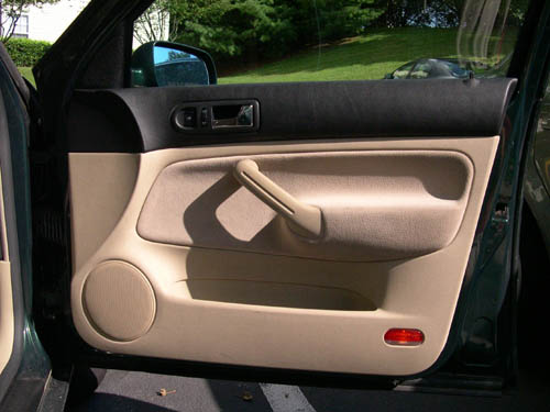
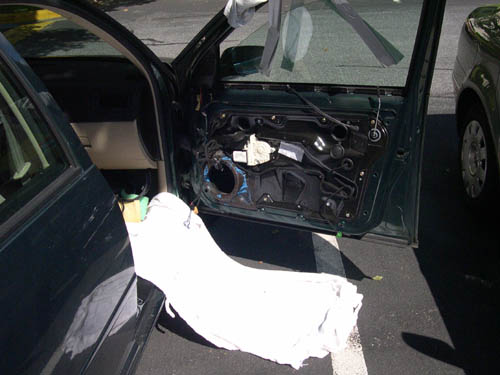
1. Remove the inner door trim panel (shown below).
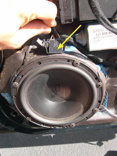
2. Once the panel is off, you should see something like this. FYI,
I have aftermarket speakers, so your woofers will look different
if you have stock speakers. Also, there is some Dynamat on my window
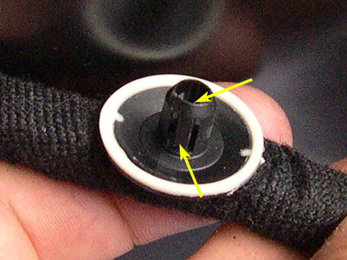
regulator carrier panel (the black panel bolted to the inside of
the door) surrounding the woofer. This is not present on a stock
panel.

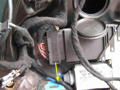
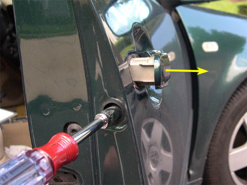
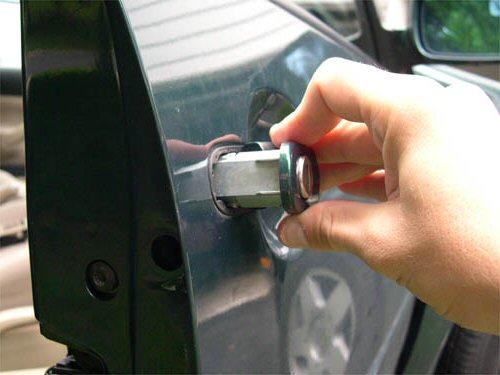
3. Disconnect the harness connector from the top of the woofer. The
approximate location of the connector on a stock woofer is shown
below.
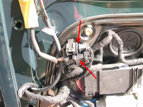
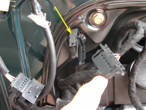
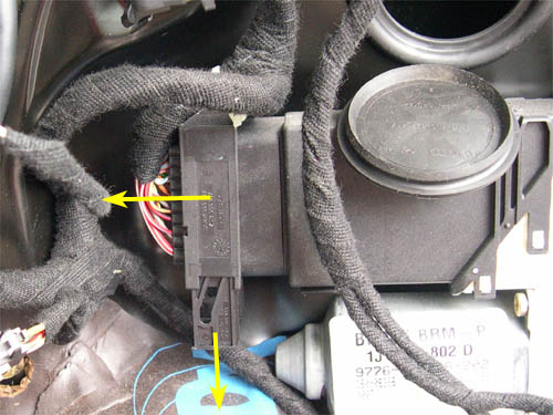
4. Disconnect the harness connectors for the tweeter and side-view
mirror, indicated by the red arrows in the picture below.
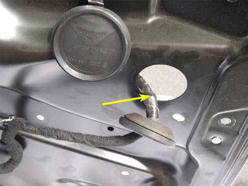
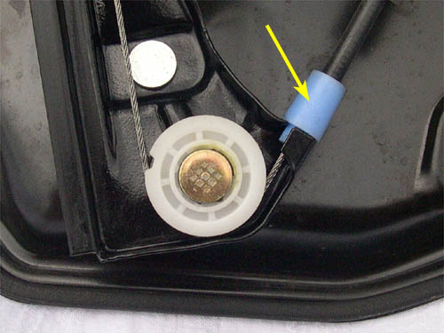
5. Remove the harnesses from the harness carrier (indicated by the
yellow arrow), as shown below.
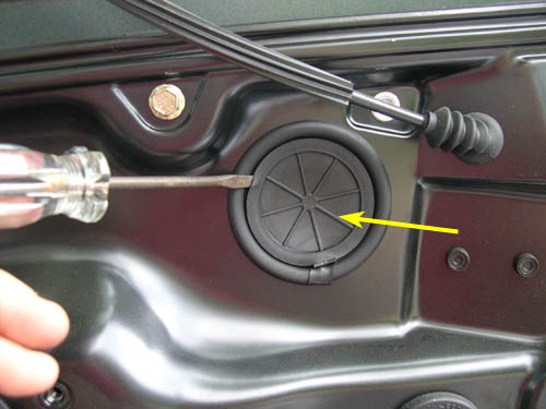
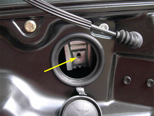
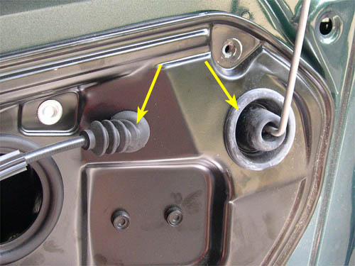
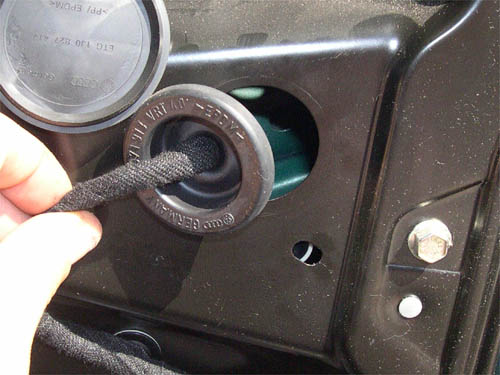
6. Using a screwdriver, unplug the two rubber grommets that cover
the access holes for the window regulator clips. One of the grommets
is shown below.
7. If your window still works (i.e., the clips have not completely
broken and the window still moves up and down), continue on with
step 8 through 11 and then go directly to step 13 (skip step 12).
If your window has fallen into the door, go directly to step 12.
8. Depending on the current position of the window, raise/lower the window so that the window regulator clips at the bottom of the window can be seen through the access holes, as shown below. Since the door panel is off, you'll need to use the window controls on the 'other' door to do this.
9. The next step is to temporarily support the window glass while
the regulator clips are being changed. Place a rag over the top
of the door. Apply a piece of duct tape to the outside of the window,
up and over the top of the door and then to the inside of the window.
I recommend doing this diagonally with two opposing pieces of tape,
as shown below.
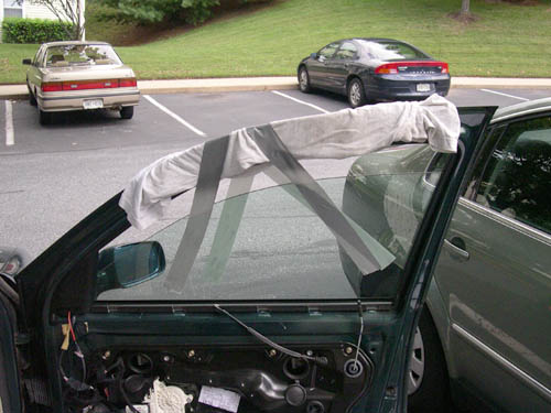
ATTENTION: Please make sure to completely secure the window
with the duct tape. The removal of the window regulator carrier
panel requires that the entire weight of the window glass be supported
by the tape. For this reason, I only recommend using duct tape.
Other types of tape may not be able to support the weight of the
window glass. Since the window may have to be supported by the
tape for 1-2 hours or more, periodically check to make sure the
tape is holding properly and is not peeling away from the glass.
If this occurs, the window glass may fall into the door and shatter!
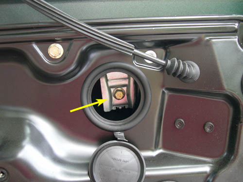
10. Remove the 10mm bolt that secures each window regulator clip (two total) to the window glass, as shown below. If you are only replacing the door lock module (i.e., not replacing the clips), you do not need to remove the bolt, only loosen it.
11. Lower the window regulator clips approximately 4-6" using the
window controls on the 'other' door. The clips should disconnect
from the bottom of the window - this will help in removing the carrier
panel later on. Go directly to step 13 (skip step 12).
12. If the regulator clips fail and the window falls into the door, it can be difficult to remove the carrier panel since the window often 'gets in the way'. If possible, try to remove the window from the door completely. This almost definitely requires the help of a second person. Attempt to pull the window up by its top edge. If you can raise the window nearly out of the door, it probably means that both clips have definitely failed. Try to raise the window so that the clips can be seen through the access holes described in step 8. If this is possible, remove the 10mm bolts, as described in step 10 and slide the clips off. Once the clips are off, remove the window from the door by pulling it up and out of the door. This is easiest if you rotate the rear edge out first and pivot the window around the lower front corner toward the front of the car. The window should come out of the door easily. If you're successful in doing this, put the window aside in a safe place. If you are not able to remove the window from the door (because it wasn't possible, not because you didn't try), it may mean that one of the regulator clips is still fully or partially intact. If this is the case, you may have to improvise a little during later steps to remove the carrier panel. I can't be more specific about this problem, since each different situation will have it's own solution.
ATTENTION: Please be extremely careful when removing the window glass from the door. Make sure to have a strong grip on the glass at all times or it may fall and break.
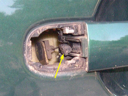
13. Disconnect the harness connector from the regulator motor by pulling down on the retaining slide, as shown below.
14. As you pull down on the retaining slide, the harness connector
will slide toward the front of the car and off of the regulator
motor, as shown below.
15. Check to see if the door lock module is riveted to the carrier
panel, as shown in the picture below. Normally, the lock module
is riveted to the panel, but if your regulator clips have been
replaced already, the rivets may not be present. VW techs are notorious
for not reinstalling the rivets when replacing the regulator clips.
If your lock module is not riveted to the panel, perform step 16.
If your lock module is riveted to the panel, you have two options.
You can (1) drill out the rivets and continue on with step 16 or
you can (2) leave the rivets intact and go directly to step 17.
Option 2 is the preferred method since the rivets can be reused
when reinstalling the carrier panel on the door - new rivets will
not need to be purchased. If you plan on replacing the door lock
module, you must perform all of the related steps (16 through 24
- do not skip any of these steps).
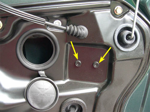
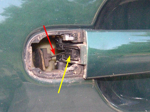
16. Pop off the rubber grommets for the inner door handle release cable
and the door lock pin (indicated by the yellow arrows in the picture
below) and then push the grommets through their respective holes in
the carrier panel.
After doing this, go directly to step 25 - Do not perform steps 17-24 unless you are replacing the door lock module.
If you are fitting our Delock Kit perform steps 17-20 & then go to step 25.
If you are replacing the door lock module, you MUST continue on with step 17.
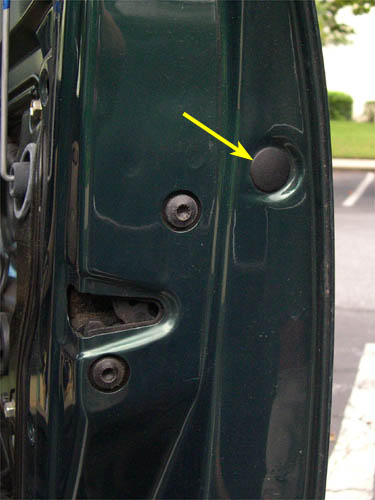
17. Remove the small plastic tab on the rear edge of the door with
a screwdriver. The tab is indicated by the yellow arrow in the
picture below.
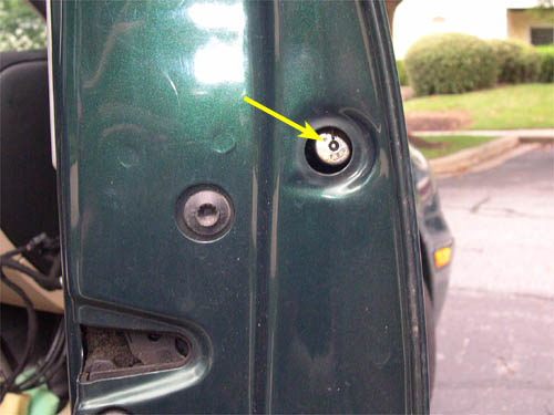
18. Behind the plastic tab is a retaining screw which is used to
secure the blank in the door handle, indicated by the yellow arrow
in the picture below. On the driver's side door, the screw secures
the piece which surrounds the door lock key slot.
19. Loosen (but do not completely remove) the retaining screw with
a T20 Torx driver. The screw actually has a very small triple square
head, but a T20 driver works perfectly. The retaining screw can
be seen in the picture below.
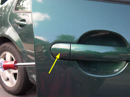
20. Loosen the retaining screw enough so that the handle blank slides
out of the door. The passenger's and driver's side pieces can be
seen in the pictures below. On my car, the screws needed to be
turned approximately 13-15 turns for the pieces to slide out. Also,
you may need to pull out on the door handle slightly to allow each
piece to slide completely out.
21. The outer handle is connected to the door lock module by a small
cable (red arrow in picture below). The end of the cable is secured
to the handle by a small plastic tab (yellow arrow in picture below)
which fits into a threaded groove.
22. Pop the tab on the end of the cable out of its retaining groove
using a small screwdriver, as shown below. Before doing this, note
the position of the tab in the groove so that it can be reinstalled
in approximately the same position later.
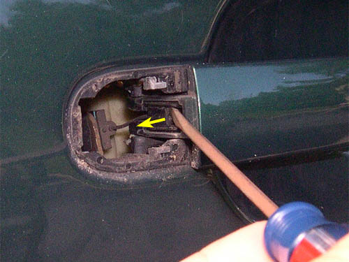
23. The picture below shows the tab detached from the retaining groove.
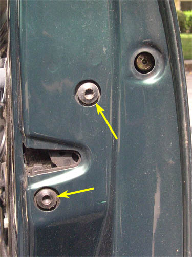
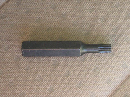
24. Remove the two door lock module bolts on the rear edge of the
door using the 8mm triple square tool. The bolts are indicated
by the yellow arrows in the picture below. The 8mm triple square
tool is also shown below.
25. Pop off the rubber grommet and push in the wire loom retaining
clip indicated by the yellow arrows in the picture below.
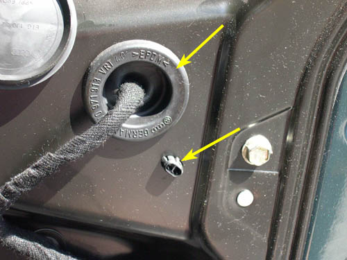
26. The grommet and retaining clip should look like they do in the
picture below when step 25 is completed.
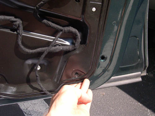
27. Put a sheet or blanket on the ground below the door and over
the door sill (as shown below) to protect the sill and carrier
panel when the panel is removed from the door.
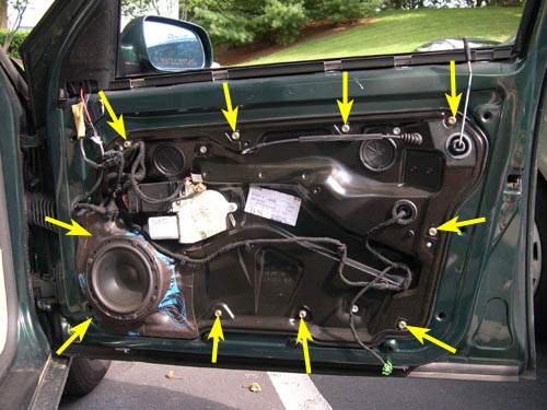
28. Remove the ten (10) 10mm bolts that secure the carrier panel
to the door. The locations of the bolts are indicated by the yellow
arrows in the picture below.
29. Starting at the rear bottom corner of the panel, pull the bottom
of the panel away from the door slightly, as shown below. You may
have to move the panel up or down slightly to wiggle the bottom
of the panel out of the door. This step may be very difficult to
perform if the window glass is still sitting at the bottom of the
door, especially if one of the regulator clips is still attached
to the bottom of the window. If this is the case, then this is
the point in the DIY that you might have to be creative in order
to complete the removal of the carrier panel from the door.
30. While holding the bottom of the panel away from the door (and
also supporting its weight), reach behind the panel from below
and push the six (6) wire loom retaining clips out of the panel.
The locations of the clips are indicated by the yellow arrows in
the picture below. If you yank on the clips from the front of the
panel, you will almost surely damage them, making it difficult
to reattach them when reinstalling the panel.

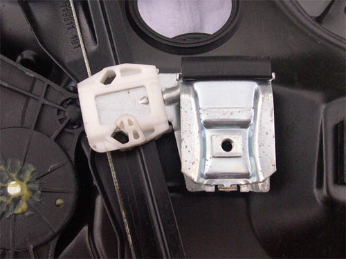
31. A close-up of one of the wire loom retaining clips is shown below.
The clips are held in place by small tabs on opposite sides of
the clip, indicated by the yellow arrows. Push in on these tabs
simultaneously and push the clip out of the panel.
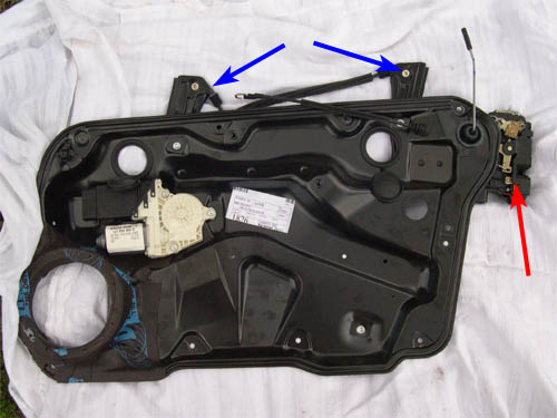
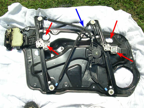
32. Once the tabs are out, lift up on the panel slightly, pull the
bottom of the panel away from the door, and then lower the panel
toward the ground and toward the front of the car. It is necessary
to do this because the window tracks extend above the top of the
carrier panel inside the door (blue arrows in picture below) and
the door lock module extends to the right of the panel inside the
door (red arrow in picture below). If you are removing the carrier
panel with the door lock module still bolted to the edge of the
door, you do not need to slide the carrier panel toward the front
of the car when removing it since the lock module is not attached
and will not impede its motion. You'll only need to lower the panel
so that the window tracks clear. Also pay careful attention to
the inner door handle cable and door lock pin when removing the
panel as they are attached to the door lock module and must slide
out of the panel.
33. Once the panel is removed from the door, disconnect the harness
connector for the door lock module by pressing down on the tab
indicated by the yellow arrow in the picture below and then sliding
the harness connector away from the lock module. (FYI, the lock
module on the driver's side door is shown in the picture below
in case someone notices some inconsistencies in the appearance
of the harness/lock module relative to the carrier panel.)

34. Pull the door lock module wire bunch (indicated by the yellow
arrow in the picture below) and harness connector through the hole
in the carrier panel. The panel should now be completely disconnected
from the door. 
35. If you plan on replacing the window regulator clips, go directly
to Part II (below).
As always, do this procedure at your own risk. I am not responsible
for any mistakes in the procedure or those that you make while
performing it.
PART II - REPLACING THE WINDOW REGULATOR CLIPS
Steps 1 through 5 provide some background info on how the old-design window regulator clips break, the differences between the old- and new-design clips and how the window regulator assembly works. The actual replacement of parts begins with step 6.
1. An intact, old-design window regulator clip can be seen in the picture below. The old-design clips are a two part design - a metal clamp (which attaches to the bottom of the window glass) which slides into a plastic support. The plastic support slides up and down the window regulator track via an L-groove (right angle) in the support and is connected to a motor by a set of opposing cables - one moves the clip down the track and one moves it up the track.
2. A broken, old-design window regulator clip can be seen in the picture
below. The old-design clip fails when the plastic support cracks and
pieces break off. This allows the metal clamp portion of the clip to
fall out of the plastic support, often resulting in the window falling
into the door (usually when both clips fail). My original clips were
replaced after 4.5 years. On both the driver's and passenger's side
doors, one of the two clips was found to be broken when the window regulator
carrier panel was removed. I have no idea how long the clips were broken
and how much longer the remaining intact clips would have lasted. I
consider myself extremely lucky not to have had a window fall into the
door. Only closing the doors with the windows fully closed (I was afraid
of the clips breaking) probably had something to do with the clips lasting
this long.

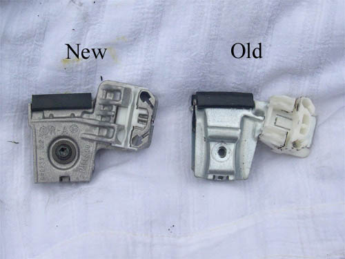
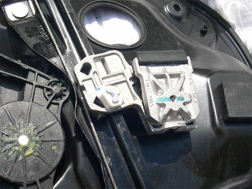
3. The differences between the old- and new-design regulator clips can
be seen in the picture below. While the old clip is a two-piece metal/plastic
design, the new clip is a one-piece metal (pot metal) design with a
small plastic L-groove sleeve insert to allow for easy sliding on the
window track. The new-design clip is considerably stronger than the
old design and should have been used from the beginning (would have
saved VW and its customers a zillion headaches).
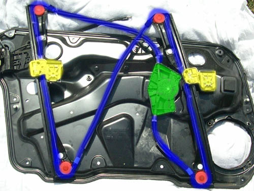
4. The colorized image below illustrates how the window regulator system
works. The window glass is raised up and down by a set of clips (yellow)
that attach to the bottom of the glass. The clips are raised up and
down by a set of opposing cables (blue) which travel around a set of
pulleys (red) and are controlled by a drive unit which consists of a
cable take-up reel (green) and an electric motor (behind the take-up
reel on the other side of the carrier panel). The cable network is setup
(uses a criss-cross pattern) so that both clips move up and down at
the same time.
5. The colorized image below illustrates how the take-up reel unit works.
Inside the unit is a wheel (yellow) which has the opposing cables (blue
and red) wrapped around it in opposite directions. Therefore, as the
window motor rotates the cable wheel, one cable is let out while the
other is wound in around the wheel. The springs on either end of the
take-up reel unit assure that the cables always remain tight (even when
the clips fail and the window falls into the door) and that the window
operates smoothly.
6. The replacement of the window regulator clips begins with the determination
of whether or not the cable/take-up reel assembly supplied in the Window
Regulator Repair Kit will also be replaced. The cable/take-up reel
assembly is not an improved part - only the regulator clips have been
redesigned. The cable/take-up reel assembly only needs to be replaced
if the cable or take-up reel unit was damaged if/when the original clips
broke and the window fell into the door. If your existing cables are
OK, you do not need to replace the cable/take-up reel assembly when
replacing the regulator clips.
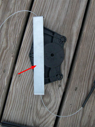
7. The cable/take-up reel assembly supplied with the Window Regulator Repair Kit can be seen in the picture below. The take-up reel assembly comes with a steel bracket attached which is used to keep the adjusting springs compressed while the assembly is not installed on the carrier panel. This bracket makes it significantly easier to replace the regulator clips and is why VW supplies it with the new cable/take-up reel assembly. It is still possible to change the regulator clips without the bracket, but doing so requires that the springs be compressed manually while trying to reinstall the regulator cables around the pulleys (this will make more sense later on).
8. If you are replacing the cable/take-up reel assembly, leave the bracket
in place on the new assembly and go directly to step 9. If you are not
replacing the cable/take-up reel assembly, remove the bracket from the
new assembly (be very careful - the springs are under considerable tension)
and slide it onto the old cable/take-up reel assembly which is attached
to the carrier panel, as shown below. If you're doing this step, make
sure that the bracket is slid onto the old assembly completely. You
don't want the bracket to accidentally pop off the assembly when the
tension is off the cables and the cables are removed from the pulleys
(this will also make more sense later on). Go directly to step 10 (skip
step 9).
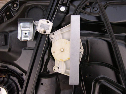
9. Remove the regulator motor from the front side of the carrier panel
(the side opposite where the clips, cables, etc are) so that the take-up
reel unit on the back side of the panel can be removed. To do this,
remove the three (3) T30 Torx screws indicated by the yellow arrows
in the picture below and pull the motor assembly off of the carrier
panel. Do NOT attempt to remove the cable/take-up reel assembly
off of the other side of the carrier panel at this time.

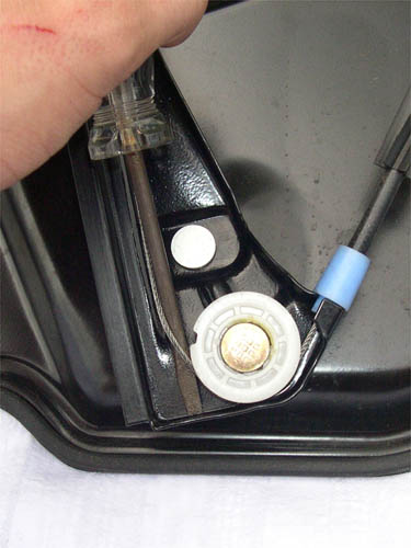
10. Using a screwdriver, pry the cable off of one of the pulleys on
the carrier panel, as shown below. The bottom rear pulley (closest to
the rear of the car when the carrier panel is installed and closest
to the ground) is shown in the picture below. Once the cable is removed
from one of the pulleys, there should no longer be any tension on the
cable and it can be easily removed from around the other pulleys. If
you are replacing the cable/take-up reel assembly, remove the cable
from the bottom front and top rear pulleys only - the cable can be left
in place around the other two pulleys (top front and bottom rear). If
you are not replacing the cable/take-up reel assembly, you only need
to remove the cable from one of the pulleys - it doesn't matter which
one you choose. Note: It will be more difficult to remove the
cable from the first pulley with the screwdriver if you are planning
on replacing the cable/take-up reel assembly and did not slide the steel
spring bracket off of the new cable/take-up reel assembly and onto the
old assembly.
11. Steps 12 through 22 deal with the removal of the old-design clips
and the installation of the new-design clips. I RECOMMEND that you remove
and reinstall each clip completely before attempting to remove and reinstall
the other clip (i.e, perform steps 12 through 22 on only one clip at
a time). It's possible to do the procedure on both clips at the same
time, but doing it on only one will help insure that the cable routings
remain in the correct position, something that may save some time when
the cables need to be reinstalled on the pulleys. Note: If you
are also replacing the cable/take-up reel assembly, you MUST
remove both clips from their cables so that the cable/take-up reel assembly
can be replaced.
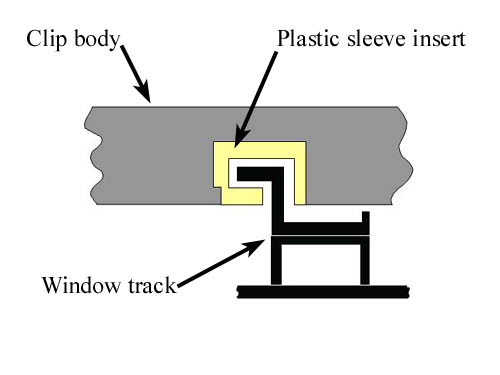
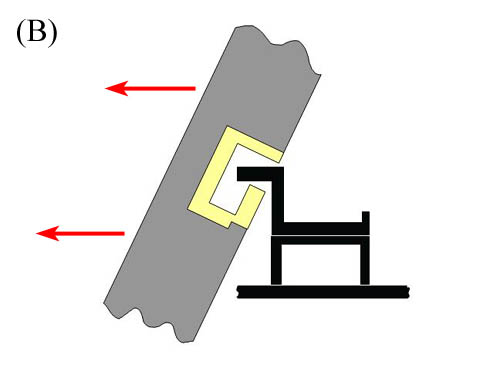
12. The schematic below shows a cross-section of a new-design clip in place on the window track (the old-design clip attaches to the track in exactly the same way - the only difference in the schematic would be the design of the clip itself). The schematic clearly shows how the window track fits into an L-groove in the clip body (on the new-design clip, the L-groove is in a plastic sleeve that is an insert in the clip body, as shown below).
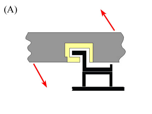
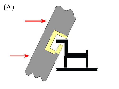
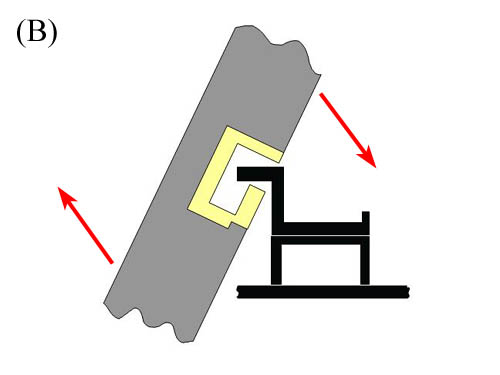
13. To remove the old clip from the window track, rotate the clip body
away from the window track (A) and then slide the clip off of the track
(B), as shown in the schematics below. In some cases, the carrier panel
itself may interfere with the rotation of the clip illustrated in schematic
(A). You may need to slide the clip up or down the window track (depending
on which clip and which pulley the cable was removed from) to an area
where rotation is unimpeded. If this is not possible, you may need to
remove the cable from another pulley to create some more slack in the
cable. If it's still not possible to remove the clips, you can always
remove the cable from around all of the pulleys - this should allow
you to move the clips fully up or down the window track.
14. The picture below shows a side view of an old-design clip body where
the cables attach (actually one of the broken clips). The cables fit
into grooves on the underside of the clip body. One of the grooves is
deeper than the other - the cable in the deeper groove needs to be removed
last and installed first.
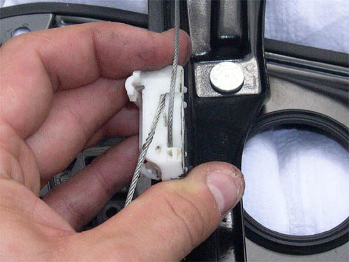
15. A picture of the underside of the clip body (below) shows how the
cables are secured in the body. There is a small cable stop on the end
of each cable which fits into a hole on the underside of the clip body.
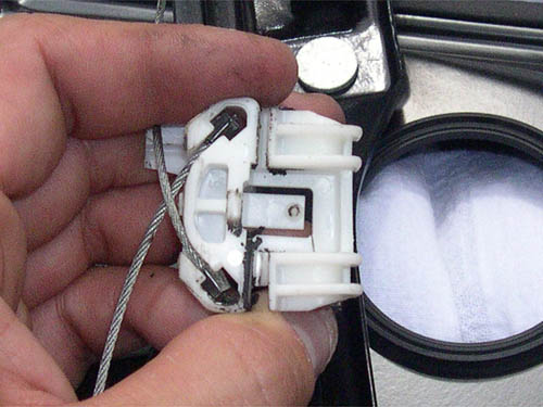
16. To remove the cable ends from the clip body, remove the cable from
its groove (start with the cable in the more shallow groove) and rotate
the cable around the stop until the cable is roughly perpendicular to
the clip body, as shown below. Then simply pull the cable stop out of
the clip body.
17. If you are replacing the cable/take-up reel assembly, remove the
old assembly from the carrier panel (it should just pop off) and then
install the new one in the same spot. Before doing so, take notice of
how the cables coming out of the cable/take-up reel assembly are routed.
When installing the new assembly, make sure to route the cable that
comes out of the top of the assembly underneath the diagonal cable between
the top front and bottom rear pulleys. Once this is done, reinstall
the window regulator motor on the front side of the carrier panel. If
you are not replacing the cable/take-up reel assembly, go directly to
step 18.
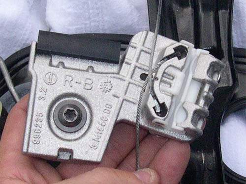
18. Before installing the cables into the new-design clip body, make sure that you have the correct clip for whatever door and window track you are working on. The four regulator clips (both new and old) are all different and will only work on their corresponding window track. The new clips are labeled with a code that indicates the door and window track that the clip should be installed on. 'L' and 'R' indicate that the clips are for the left and right doors, respectively. 'A' and 'B' indicate that the clips are for the front (towards the front of the car when the carrier panel is installed on the door) and rear window tracks, respectively. For example, a clip with the code 'R-B' should be installed on the right door on the rear window track. Similarly, a clip with the code 'L-A' should be installed on the left door on the front window track. Also, before installing the cables on the new clip, make sure to loosen the T30 Torx screw on the clip so that the window will slide into it easily later on. Do not remove the bolt completely - only loosen it.
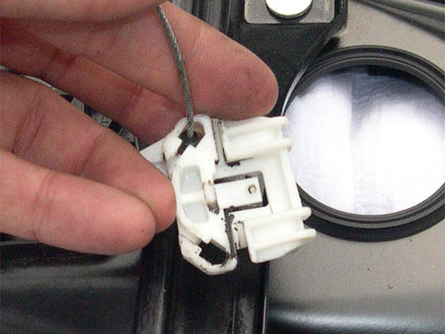
19. Install the cables into the new-design clip body by following step 16 in reverse. Remember to install the appropriate cable into the deeper groove first. The cables should appear as they do in the picture below after being installed.
20. On the side of the clip, there is a small tab which separates the
two cables and keeps them from rubbing against each other. Make sure
that one of the cables runs on one side of the tab and the other cable
runs on the other side of the tab.
21. Now it's time to install the new-design clip onto the window track
- the schematics below indicate how to do this. The process is basically
the exact opposite of the removal of the old-design clips from the window
track. Simply insert the edge of the window track into the plastic L-groove
insert in the new clip (A) and then rotate the clip body into place
on the track (B).
22. The picture below shows a new-design window regulator clip installed
onto the window track.
23. If you did not remove and replace both regulator clips at the same
time (for whatever reason), remove and replace the regulator clip on
the other window track by following steps 12 through 22.
24. Once both regulator clips have been replaced, it's time to reinstall the regulator cable on the pulleys. Make sure that the cable is installed correctly on three of the four pulleys and then use a screwdriver to pop the cable onto the fourth and final pulley. Make sure that the cable guide (indicated by the yellow arrow in the picture below - there is one for each pulley) is in position. This procedure should be relatively easy if the steel spring bracket is in place on the cable/take-up reel assembly. If it is not, you'll need to compress the springs on the assembly by hand to provide enough slack for the cable to be installed on the final pulley. It helps to have a second person compress the springs while you install the cable on the pulley. Newer pulleys have a cam pulley molded on top of each cable pulley which can be used to assist in reinstalling the cables if need be (Sorry. I don't have a picture). To use the cams, install the cable on one or more of the cams instead of directly on the main pulleys - use as many cams as necessary to provide enough slack to get the cable on all four cams/pulleys. Once the cable is in place on the four cams/pulleys, pull down or push up on the two regulator clips simultaneously. This will force the clips to move and will cause the cables to rotate on the cams/pulleys. After moving the clips a short distance, the cams will pop the cable onto the main pulley - move the clips until the cable is correctly installed on all four main pulleys.
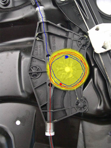
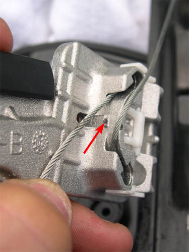
25. Once the cable has been reinstalled on pulleys, double check to
make sure that the clip replacement process has been done correctly.
First, make sure that the new regulator clips line up with the access
holes in the carrier panel (red arrows in picture below). If they do
not, you'll need to reinstall the clips in the correct locations. Next,
make sure that the cable coming out of the top of the cable/take-up
reel assembly passes underneath the other diagonal cable, as indicated
by the blue arrow in the picture below. Finally, make sure that the
cables sit on opposite sides of the small tab on the edge of the clip
bodies, as described in step 20. If the above three conditions are met,
then the new regulator clips should be installed correctly.
26. Remove the steel spring bracket from the cable/take-up reel assembly.
The window regulator system should now be fully operational.
27. Reinstall the carrier panel back onto the door
As always, do this procedure at your own risk. I am not responsible for any mistakes in the procedure or those that you make while performing it.
Many
Thanks to VgRt6 @ vwvortex.com for this Repair Guide